Shanghai JetCutt Cutting Tools Co., Ltd. Loding...

How to Build a Repeatable Tool-Life Monitoring Routine for Carbide Inserts

Tool life is not only a cutting-tool issue; it is a process-control issue. A carbide insert may fail because of flank wear, crater wear, chipping, built-up edge, vibration, unstable clamping, or an unsuitable cutting condition. Without a repeatable monitoring routine, operators often change inserts too early, run them too long, or blame the wrong cause.

Why tool-life monitoring matters

Modern machining teams are under pressure to improve uptime, reduce scrap, and make performance repeatable across shifts. Recent tooling guidance increasingly combines insert selection with process data, machine status, and documented inspection points. Digital machine-monitoring systems can help show production interruptions and bottlenecks, but a practical tool-life routine can also start with a simple inspection sheet and consistent operator observations.

The objective is not to predict an exact replacement minute for every insert. The objective is to identify the wear pattern, define a safe replacement trigger, and create a cutting recipe that can be repeated.

Start with a clear wear baseline

Before collecting data, record the conditions that influence the cutting edge:

  • Workpiece material and hardness range
  • Insert geometry, chipbreaker, edge preparation, and grade
  • Cutting speed, feed, depth of cut, and engagement
  • Tool overhang, holder condition, clamping, and machine rigidity
  • Coolant mode, nozzle position, concentration, or MQL setting

This baseline prevents a common mistake: comparing two insert results after changing several variables at the same time. If the insert grade, feed, overhang, and coolant delivery all change together, the recorded tool-life difference cannot explain what actually improved the process.

Use a practical inspection sequence

  1. Inspect the insert seat. Remove chips and check the pocket, shim, screw, and contact surfaces. A dirty or damaged seat can create instability that looks like normal insert wear.
  2. Check the dominant wear mode. Look for flank wear, crater wear, notching, plastic deformation, chipping, built-up edge, or thermal cracking. Record the location and direction of the damage.
  3. Review the part. Note surface finish, burrs, dimensional drift, chatter marks, and chip shape. Part quality can deteriorate before the insert looks visibly damaged.
  4. Record the cutting history. Log machining time, number of parts, interrupted cuts, material changes, coolant changes, and any alarm or vibration event.
  5. Decide whether to continue, index, or replace. Use the same trigger rules for every shift. When the trigger is reached, save the insert for review instead of discarding the evidence.

Turn observations into a repeatable decision rule

A useful shop rule connects tool condition to a measurable production outcome. For example, a team may set a replacement trigger when surface finish leaves the approved range, flank wear reaches the internal limit, burrs increase, or the first sign of edge chipping appears on a safety-critical operation. The correct threshold depends on the workpiece, insert system, machine, and quality requirement; it should be validated during a controlled trial rather than copied from an unrelated application.

Observation Possible cause First check
Uniform flank wear Normal abrasion or excessive cutting temperature Grade, speed, coolant strategy, and cutting time
Edge chipping Interrupted cut, vibration, weak edge, or impact Rigidity, clamping, edge preparation, and engagement
Crater wear High temperature or strong chip sliding Cutting speed, grade, chip control, and coolant direction
Built-up edge Low or unstable cutting temperature and adhesion Speed, edge sharpness, workpiece material, and lubrication
Notching at depth-of-cut line Workpiece scale, hard layer, or localized abrasion Depth of cut, lead angle, and grade selection

Combine operator checks with machine data

Machine-monitoring tools can add context that a visual insert check cannot provide. Production status, alarms, feed changes, cycle interruptions, and operator comments help explain why two apparently identical inserts produced different results. A simple dashboard or daily spreadsheet is enough to begin: link the insert batch, machine, work order, operator, cutting recipe, and replacement reason.

Data should support technical judgement, not replace it. A machine alarm may reveal a process interruption, but it does not automatically identify whether the insert grade, chipbreaker, workholding, or coolant delivery caused the event.

How JetCutt can support the workflow

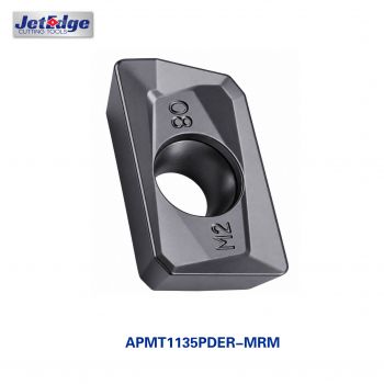
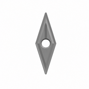
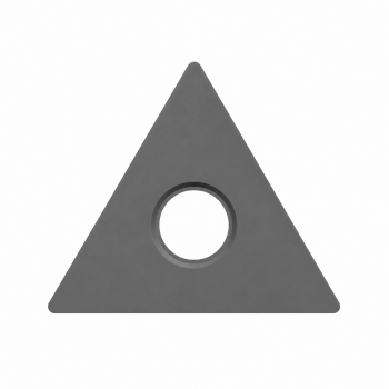
JetCutt helps distributors, tooling companies, and machining users compare carbide insert options with the application conditions that matter. Start with the workpiece and operation, then review insert geometry, grade, coating, edge preparation, chip control, and cutting data as one system. For turning applications, see the VNMG Carbide Turning Inserts and WNMG Carbide Turning Inserts ranges. For milling, review the APKT Shoulder Milling Inserts range and confirm the application with JetCutt before standardizing the recipe.

FAQ

Should every insert be replaced at the same time?

No. Replace or index an insert when its validated wear or quality trigger is reached. A blanket replacement interval may waste usable edge life or allow an unstable edge to continue cutting.

Can tool monitoring eliminate insert trials?

No. Monitoring makes trials more controlled and easier to compare, but grade, geometry, workpiece, machine, and cutting conditions still need to be validated in the real application.

What is the simplest way to start?

Use one standard record for every insert change: machine, workpiece, insert identification, cutting data, operating time, wear mode, part-quality result, and replacement reason. Review the records weekly and change one process variable at a time.

Related JetCutt guides

Further reading

Actual tool life depends on the machine, workpiece, insert geometry, grade, cutting data, setup rigidity, coolant delivery, and inspection standard. Use controlled trials and application support before adopting a production-wide replacement rule.