Shanghai JetCutt Cutting Tools Co., Ltd. Loding...

Carbide Insert Buying Checklist for OEM Machining Programs

Buying carbide inserts for an OEM machining program is not simply a matter of matching a catalog code to a part drawing. The insert must work as part of a repeatable system that includes the workpiece material, operation, toolholder, cutting data, coolant, inspection method and supply plan. A clear specification reduces trial-and-error, protects delivery schedules and makes future replacements easier to control.

This checklist gives purchasing, engineering and production teams a practical way to define carbide insert requirements before requesting samples or a quotation from a manufacturer or supplier such as JetCutt.

1. Start with the application, not the brand name

Record the actual machining conditions before comparing equivalent inserts. At minimum, document the workpiece material group, alloy or grade, hardness or heat-treatment condition, and whether the cut is continuous, interrupted, roughing, semi-finishing or finishing. Also record whether the operation is external turning, internal turning, profiling, grooving, threading or milling.

Two inserts with the same basic shape can perform very differently when the depth of cut, feed, rigidity or chip-control requirement changes. A boring-bar operation with long overhang needs a different balance of edge strength and cutting force than a short, rigid external turning setup.

2. Define the complete insert designation

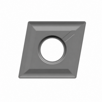
Do not quote only a family name such as “CNMG” or “carbide turning insert.” A usable OEM specification should identify the complete designation, including shape, clearance angle, tolerance class, size, thickness, corner radius, chipbreaker and hand where applicable. If the insert has a wiper or a special edge preparation, include that information as well.

Specification field Why it matters
ISO/ANSI designation Confirms mounting compatibility and basic insert dimensions.
Corner radius Balances surface finish, edge strength and radial cutting force.
Chipbreaker or geometry Controls chip formation within a defined feed and depth-of-cut window.
Grade and coating Sets the starting balance between wear resistance, toughness and cutting temperature.
Edge preparation Controls sharpness, impact resistance and cutting pressure.
Packaging and traceability Protects identification and makes replenishment and quality review repeatable.

3. Match grade and geometry to the cutting window

Insert grade selection should be linked to the workpiece and the cutting speed. Geometry selection should be linked to feed, depth of cut and operation type. A sharp geometry may reduce cutting forces and help finishing, while a stronger edge preparation can be more suitable for interrupted cuts or unstable workholding. Neither choice is universally better; the correct choice is the one that remains stable in the intended operating window.

For a new OEM program, ask the supplier to state the recommended starting range rather than providing a single isolated cutting number. The trial record should include speed, feed, depth of cut, coolant method, toolholder, insert grade and observed wear. This makes the sample evaluation useful for production instead of treating it as a one-time test.

JetCutt's existing carbide insert grade guide and cutting-data guide can be used as internal references when creating that trial sheet.

4. Specify coating and substrate expectations carefully

Coating should be selected with the material group and thermal load in mind. For many steel, stainless steel and high-temperature applications, a coated carbide grade is a practical starting point, but the coating is only one part of the system. Substrate toughness, grain structure, edge preparation and cutting data all affect the result.

Ask for the grade family, coating process, intended material groups and recommended operation range. Avoid unsupported statements such as “longer life in every material.” A professional quotation should explain where the grade is expected to work and what conditions could cause chipping, crater wear, notch wear or built-up edge.

5. Build quality checks into the purchase order

OEM purchasing should define what is checked when the inserts arrive. Useful checks include designation and quantity, insert shape, corner radius, seating surface, visible edge damage, coating appearance, packaging label and lot or batch traceability. If the part is safety-critical or dimensional stability is especially important, agree on a sampling plan and the records supplied with each lot.

For coated inserts, visual appearance alone cannot confirm cutting performance, but it can identify damaged packaging, mixed lots or obvious surface defects. Keep one unopened sample from each new lot when the program requires formal traceability.

6. Test samples using a controlled comparison

Compare one variable at a time. Keep the workpiece, holder, coolant and toolpath consistent while changing the insert grade or geometry. Measure tool life, surface finish, burr formation, chip shape, dimensional drift and the final wear pattern. If the process is unstable, check setup rigidity and chip evacuation before changing to a more expensive grade.

When chipping or unexpected wear appears, JetCutt's insert wear-monitoring routine can help separate normal flank wear from edge fracture, notch wear and built-up material. The objective is not just to find a sample that cuts; it is to document a process window that another operator can reproduce.

7. Confirm supply, replacement and technical support

A technically suitable insert is not a reliable OEM solution if the replacement plan is unclear. Confirm standard pack quantity, lead time, minimum order quantity, approved equivalents, lot identification and the process for handling a nonconforming batch. Ask whether the supplier can support sample trials, geometry changes, coating alternatives and forecast-based replenishment.

For customized or private-label programs, clarify drawing control, revision management, packaging artwork, inspection records and approval samples before production release. These details prevent a small specification change from becoming a field problem later.

OEM carbide insert buying checklist

  • Workpiece material, alloy, hardness and material condition recorded.
  • Operation, toolholder, rigidity, cutting direction and interruption level defined.
  • Complete ISO/ANSI designation, size, thickness and corner radius confirmed.
  • Chipbreaker, edge preparation, grade and coating matched to the cutting window.
  • Starting speed, feed, depth of cut and coolant method documented.
  • Incoming inspection, lot traceability and packaging requirements agreed.
  • Sample comparison method and wear-record format prepared.
  • Replacement, equivalent-product and technical-support process confirmed.

FAQ

Should an OEM buyer choose the toughest insert grade?

No. Toughness can help with interrupted cuts and unstable setups, but an overly tough grade or protected edge can increase cutting force and reduce wear resistance. Select grade, geometry and edge preparation together.

Is the insert designation enough to guarantee interchangeability?

Not always. Confirm the full designation, tolerance, corner radius, chipbreaker, hand, seating condition and the toolholder manufacturer's requirements. Special geometries and wipers can change the operating range even when the basic shape code is the same.

What should be compared during a sample trial?

Compare tool life, surface finish, chip control, dimensional stability, burrs and the final wear pattern under the same controlled conditions. Record one change at a time so the result can be repeated.

JetCutt supports carbide insert selection, samples and OEM process trials for turning, milling, grooving and threading applications. A complete specification makes it easier to compare suppliers, approve samples and build a stable production process.

Technical references